01. Table 310.16
| Size | 60°CTW, UF | 75°CRHW, THHW, THW, THWN, XHHW, USE, ZW | 90°CTBS, SA, SIS, FEP, FEPB, MI, RHH, RHW-2, THHN, THHW, THW-2, THWN-2, USE-2, XHH, XHHW, XHHW-2, ZW-2 | Max overcurrent protection under NEC 240.4(D). An em dash means see 240.4.240.4(D) |
|---|---|---|---|---|
| 7A | ||||
| 10A | ||||
| 15A | ||||
| 20A | ||||
| 30A | ||||
| not listed in 240.4(D), see 240.4 | ||||
| not listed in 240.4(D), see 240.4 | ||||
| not listed in 240.4(D), see 240.4 | ||||
| not listed in 240.4(D), see 240.4 | ||||
| not listed in 240.4(D), see 240.4 | ||||
| not listed in 240.4(D), see 240.4 | ||||
| not listed in 240.4(D), see 240.4 | ||||
| not listed in 240.4(D), see 240.4 | ||||
| not listed in 240.4(D), see 240.4 | ||||
| not listed in 240.4(D), see 240.4 | ||||
| not listed in 240.4(D), see 240.4 | ||||
| not listed in 240.4(D), see 240.4 | ||||
| not listed in 240.4(D), see 240.4 | ||||
| not listed in 240.4(D), see 240.4 | ||||
| not listed in 240.4(D), see 240.4 | ||||
| not listed in 240.4(D), see 240.4 | ||||
| not listed in 240.4(D), see 240.4 | ||||
| not listed in 240.4(D), see 240.4 | ||||
| not listed in 240.4(D), see 240.4 | ||||
| not listed in 240.4(D), see 240.4 | ||||
| not listed in 240.4(D), see 240.4 | ||||
| not listed in 240.4(D), see 240.4 | ||||
| not listed in 240.4(D), see 240.4 | ||||
| not listed in 240.4(D), see 240.4 | ||||
| not listed in 240.4(D), see 240.4 |
| Size | 60°CTW, UF | 75°CRHW, THHW, THW, THWN, XHHW, USE | 90°CTBS, SA, SIS, THHN, THHW, THW-2, THWN-2, RHH, RHW-2, USE-2, XHH, XHHW, XHHW-2, ZW-2 | Max overcurrent protection under NEC 240.4(D). An em dash means see 240.4.240.4(D) |
|---|---|---|---|---|
| 15A | ||||
| 25A | ||||
| not listed in 240.4(D), see 240.4 | ||||
| not listed in 240.4(D), see 240.4 | ||||
| not listed in 240.4(D), see 240.4 | ||||
| not listed in 240.4(D), see 240.4 | ||||
| not listed in 240.4(D), see 240.4 | ||||
| not listed in 240.4(D), see 240.4 | ||||
| not listed in 240.4(D), see 240.4 | ||||
| not listed in 240.4(D), see 240.4 | ||||
| not listed in 240.4(D), see 240.4 | ||||
| not listed in 240.4(D), see 240.4 | ||||
| not listed in 240.4(D), see 240.4 | ||||
| not listed in 240.4(D), see 240.4 | ||||
| not listed in 240.4(D), see 240.4 | ||||
| not listed in 240.4(D), see 240.4 | ||||
| not listed in 240.4(D), see 240.4 | ||||
| not listed in 240.4(D), see 240.4 | ||||
| not listed in 240.4(D), see 240.4 | ||||
| not listed in 240.4(D), see 240.4 | ||||
| not listed in 240.4(D), see 240.4 | ||||
| not listed in 240.4(D), see 240.4 | ||||
| not listed in 240.4(D), see 240.4 | ||||
| not listed in 240.4(D), see 240.4 | ||||
| not listed in 240.4(D), see 240.4 | ||||
| not listed in 240.4(D), see 240.4 | ||||
| not listed in 240.4(D), see 240.4 |
Max represents the maximum overcurrent protection rating from NEC 240.4(D) for small conductors. — indicates the size is not subject to a specific 240.4(D) cap. Refer to NEC 240.4 for general overcurrent protection rules.
Insulation types correspond to NEC Table 310.16 column classifications: Copper 60°C: TW, UF. 75°C: RHW, THHW, THW, THWN, XHHW, USE, ZW. Copper 90°C: TBS, SA, SIS, FEP, FEPB, MI, RHH, RHW-2, THHN, THHW, THW-2, THWN-2, USE-2, XHH, XHHW, XHHW-2, ZW-2. Aluminum 60°C: TW, UF. 75°C: RHW, THHW, THW, THWN, XHHW, USE. Aluminum 90°C: TBS, SA, SIS, THHN, THHW, THW-2, THWN-2, RHH, RHW-2, USE-2, XHH, XHHW, XHHW-2, ZW-2.
02. Copper and aluminum
Complete wire ampacity chart
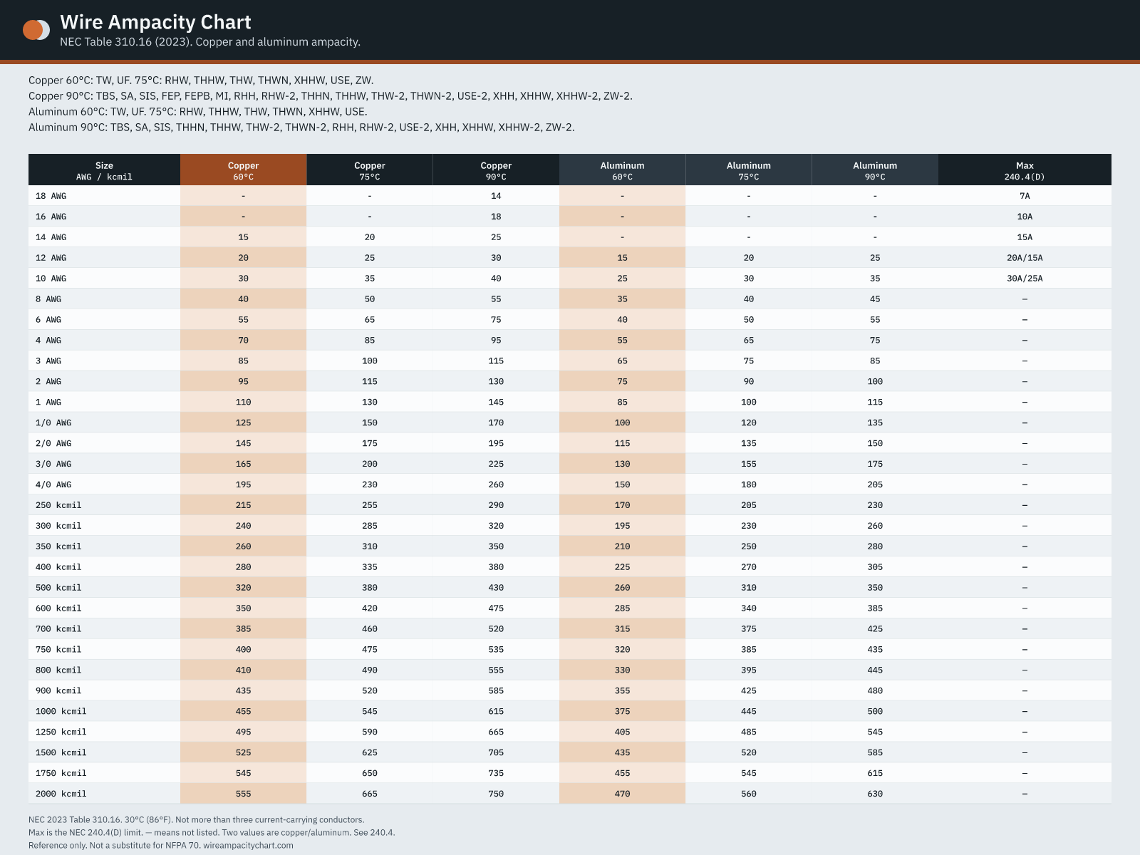
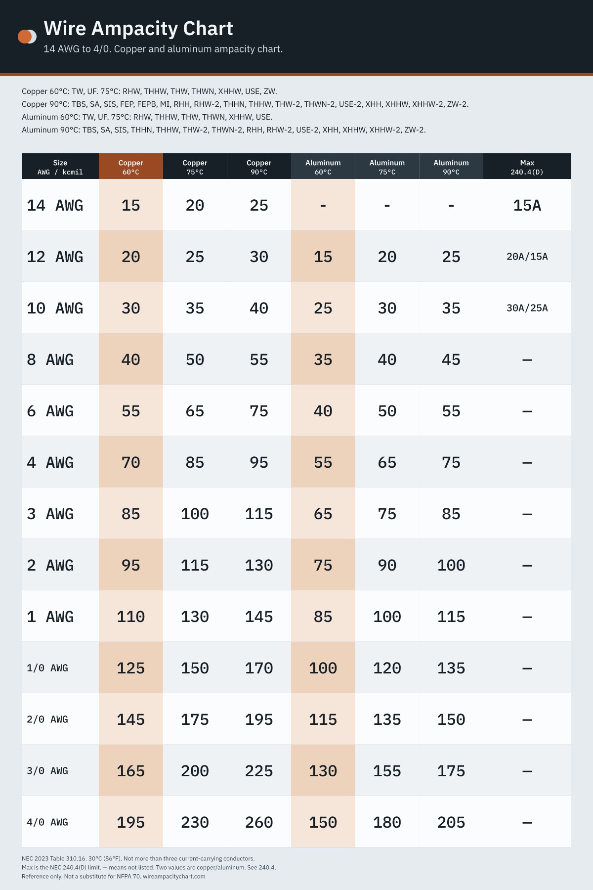
Complete ampacity ratings from NEC Table 310.16 (2023) for copper and aluminum or copper-clad aluminum conductors. A hyphen indicates the table lists no rating for that size and temperature combination.
| Size | 60°CTW, UF | 75°CRHW, THHW, THW, THWN, XHHW, USE, ZW | 90°CTBS, SA, SIS, FEP, FEPB, MI, RHH, RHW-2, THHN, THHW, THW-2, THWN-2, USE-2, XHH, XHHW, XHHW-2, ZW-2 | 60°CTW, UF | 75°CRHW, THHW, THW, THWN, XHHW, USE | 90°CTBS, SA, SIS, THHN, THHW, THW-2, THWN-2, RHH, RHW-2, USE-2, XHH, XHHW, XHHW-2, ZW-2 |
|---|---|---|---|---|---|---|
| 18AWG | - | - | 14 | - | - | - |
| 16AWG | - | - | 18 | - | - | - |
| 14AWG | 15 | 20 | 25 | - | - | - |
| 12AWG | 20 | 25 | 30 | 15 | 20 | 25 |
| 10AWG | 30 | 35 | 40 | 25 | 30 | 35 |
| 8AWG | 40 | 50 | 55 | 35 | 40 | 45 |
| 6AWG | 55 | 65 | 75 | 40 | 50 | 55 |
| 4AWG | 70 | 85 | 95 | 55 | 65 | 75 |
| 3AWG | 85 | 100 | 115 | 65 | 75 | 85 |
| 2AWG | 95 | 115 | 130 | 75 | 90 | 100 |
| 1AWG | 110 | 130 | 145 | 85 | 100 | 115 |
| 1/0AWG | 125 | 150 | 170 | 100 | 120 | 135 |
| 2/0AWG | 145 | 175 | 195 | 115 | 135 | 150 |
| 3/0AWG | 165 | 200 | 225 | 130 | 155 | 175 |
| 4/0AWG | 195 | 230 | 260 | 150 | 180 | 205 |
| 250kcmil | 215 | 255 | 290 | 170 | 205 | 230 |
| 300kcmil | 240 | 285 | 320 | 195 | 230 | 260 |
| 350kcmil | 260 | 310 | 350 | 210 | 250 | 280 |
| 400kcmil | 280 | 335 | 380 | 225 | 270 | 305 |
| 500kcmil | 320 | 380 | 430 | 260 | 310 | 350 |
| 600kcmil | 350 | 420 | 475 | 285 | 340 | 385 |
| 700kcmil | 385 | 460 | 520 | 315 | 375 | 425 |
| 750kcmil | 400 | 475 | 535 | 320 | 385 | 435 |
| 800kcmil | 410 | 490 | 555 | 330 | 395 | 445 |
| 900kcmil | 435 | 520 | 585 | 355 | 425 | 480 |
| 1000kcmil | 455 | 545 | 615 | 375 | 445 | 500 |
| 1250kcmil | 495 | 590 | 665 | 405 | 485 | 545 |
| 1500kcmil | 525 | 625 | 705 | 435 | 520 | 585 |
| 1750kcmil | 545 | 650 | 735 | 455 | 545 | 615 |
| 2000kcmil | 555 | 665 | 750 | 470 | 560 | 630 |
| Size | 60°CTW, UF | 75°CRHW, THHW, THW, THWN, XHHW, USE, ZW | 90°CTBS, SA, SIS, FEP, FEPB, MI, RHH, RHW-2, THHN, THHW, THW-2, THWN-2, USE-2, XHH, XHHW, XHHW-2, ZW-2 |
|---|---|---|---|
| 18AWG | - | - | 14 |
| 16AWG | - | - | 18 |
| 14AWG | 15 | 20 | 25 |
| 12AWG | 20 | 25 | 30 |
| 10AWG | 30 | 35 | 40 |
| 8AWG | 40 | 50 | 55 |
| 6AWG | 55 | 65 | 75 |
| 4AWG | 70 | 85 | 95 |
| 3AWG | 85 | 100 | 115 |
| 2AWG | 95 | 115 | 130 |
| 1AWG | 110 | 130 | 145 |
| 1/0AWG | 125 | 150 | 170 |
| 2/0AWG | 145 | 175 | 195 |
| 3/0AWG | 165 | 200 | 225 |
| 4/0AWG | 195 | 230 | 260 |
| 250kcmil | 215 | 255 | 290 |
| 300kcmil | 240 | 285 | 320 |
| 350kcmil | 260 | 310 | 350 |
| 400kcmil | 280 | 335 | 380 |
| 500kcmil | 320 | 380 | 430 |
| 600kcmil | 350 | 420 | 475 |
| 700kcmil | 385 | 460 | 520 |
| 750kcmil | 400 | 475 | 535 |
| 800kcmil | 410 | 490 | 555 |
| 900kcmil | 435 | 520 | 585 |
| 1000kcmil | 455 | 545 | 615 |
| 1250kcmil | 495 | 590 | 665 |
| 1500kcmil | 525 | 625 | 705 |
| 1750kcmil | 545 | 650 | 735 |
| 2000kcmil | 555 | 665 | 750 |
| Size | 60°CTW, UF | 75°CRHW, THHW, THW, THWN, XHHW, USE | 90°CTBS, SA, SIS, THHN, THHW, THW-2, THWN-2, RHH, RHW-2, USE-2, XHH, XHHW, XHHW-2, ZW-2 |
|---|---|---|---|
| 12AWG | 15 | 20 | 25 |
| 10AWG | 25 | 30 | 35 |
| 8AWG | 35 | 40 | 45 |
| 6AWG | 40 | 50 | 55 |
| 4AWG | 55 | 65 | 75 |
| 3AWG | 65 | 75 | 85 |
| 2AWG | 75 | 90 | 100 |
| 1AWG | 85 | 100 | 115 |
| 1/0AWG | 100 | 120 | 135 |
| 2/0AWG | 115 | 135 | 150 |
| 3/0AWG | 130 | 155 | 175 |
| 4/0AWG | 150 | 180 | 205 |
| 250kcmil | 170 | 205 | 230 |
| 300kcmil | 195 | 230 | 260 |
| 350kcmil | 210 | 250 | 280 |
| 400kcmil | 225 | 270 | 305 |
| 500kcmil | 260 | 310 | 350 |
| 600kcmil | 285 | 340 | 385 |
| 700kcmil | 315 | 375 | 425 |
| 750kcmil | 320 | 385 | 435 |
| 800kcmil | 330 | 395 | 445 |
| 900kcmil | 355 | 425 | 480 |
| 1000kcmil | 375 | 445 | 500 |
| 1250kcmil | 405 | 485 | 545 |
| 1500kcmil | 435 | 520 | 585 |
| 1750kcmil | 455 | 545 | 615 |
| 2000kcmil | 470 | 560 | 630 |
Insulation types correspond to NEC Table 310.16 column classifications: Copper 60°C: TW, UF. 75°C: RHW, THHW, THW, THWN, XHHW, USE, ZW. Copper 90°C: TBS, SA, SIS, FEP, FEPB, MI, RHH, RHW-2, THHN, THHW, THW-2, THWN-2, USE-2, XHH, XHHW, XHHW-2, ZW-2. Aluminum 60°C: TW, UF. 75°C: RHW, THHW, THW, THWN, XHHW, USE. Aluminum 90°C: TBS, SA, SIS, THHN, THHW, THW-2, THWN-2, RHH, RHW-2, USE-2, XHH, XHHW, XHHW-2, ZW-2.
03. Downloads
Download the wire ampacity chart
High-resolution PNG reference charts and a printable PDF document, generated directly from the official NEC 2023 Table 310.16 values.
04. Ambient correction
Ambient temperature correction
Correction factors from NEC Table 310.15(B)(1) based on a 30°C (86°F) ambient temperature. Multiply the Table 310.16 ampacity by the factor corresponding to the conductor's insulation temperature rating.
| Ambient °C | Ambient °F | 60°C | 75°C | 90°C |
|---|---|---|---|---|
| 10 or less | 50 or less | 1.29 | 1.20 | 1.15 |
| 11–15 | 51–59 | 1.22 | 1.15 | 1.12 |
| 16–20 | 60–68 | 1.15 | 1.11 | 1.08 |
| 21–25 | 69–77 | 1.08 | 1.05 | 1.04 |
| 26–30 | 78–86 | 1.00 | 1.00 | 1.00 |
| 31–35 | 87–95 | 0.91 | 0.94 | 0.96 |
| 36–40 | 96–104 | 0.82 | 0.88 | 0.91 |
| 41–45 | 105–113 | 0.71 | 0.82 | 0.87 |
| 46–50 | 114–122 | 0.58 | 0.75 | 0.82 |
| 51–55 | 123–131 | 0.41 | 0.67 | 0.76 |
| 56–60 | 132–140 | - | 0.58 | 0.71 |
| 61–65 | 141–149 | - | 0.47 | 0.65 |
| 66–70 | 150–158 | - | 0.33 | 0.58 |
| 71–75 | 159–167 | - | - | 0.50 |
| 76–80 | 168–176 | - | - | 0.41 |
| 81–85 | 177–185 | - | - | 0.29 |
05. More than three conductors
More than three current-carrying conductors
Adjustment factors from NEC Table 310.15(C)(1). Apply the derating percentage to the Table 310.16 ampacity after applying any ambient temperature correction.
| Number of conductors | Percent of Table 310.16 |
|---|---|
| 4–6 | 80% |
| 7–9 | 70% |
| 10–20 | 50% |
| 21–30 | 45% |
| 31–40 | 40% |
| 41 and above | 35% |
06. Questions
Ampacity chart questions
- What is an ampacity chart?
- An ampacity chart specifies the maximum current, in amperes, that a conductor can carry continuously under specific operating conditions without exceeding its insulation temperature rating. This chart is based on NEC Table 310.16 (2023), which applies to not more than three current-carrying conductors installed in a raceway, cable, or direct burial in earth, at a design ambient temperature of 30°C (86°F).
- Why is 14 AWG copper limited to a 15 A breaker?
- While NEC Table 310.16 lists the allowable ampacity for 14 AWG copper as 15 A at 60°C, 20 A at 75°C, and 25 A at 90°C, NEC 240.4(D)(3) mandates that overcurrent protection for small conductors must not exceed 15 A. Similar limits apply to 12 AWG copper (20 A) and 10 AWG copper (30 A), unless explicitly permitted under 240.4(E) or (G). Therefore, you cannot size the circuit breaker purely from the 75°C or 90°C columns.
- When can I use the 75°C column instead of 60°C?
- Standard residential branch circuits typically require sizing from the 60°C column per NEC 110.14(C). The 75°C column may only be utilized when both the conductor insulation and all connected equipment terminals, breakers, and devices are explicitly rated for 75°C or higher. Even when using a conductor with 90°C insulation landed on 75°C terminals, the ampacity must be determined from the 75°C column, as the lowest-rated element in the circuit governs the allowable capacity.
- How do I apply ambient temperature correction?
- Table 310.16 base values assume an ambient temperature of 30°C (86°F). If conductors operate in an environment with higher or lower ambient temperatures, you must multiply the table ampacity by the appropriate correction factor from NEC Table 310.15(B)(1) for the conductor's temperature rating. Any small-conductor limits under NEC 240.4(D) are enforced after all correction factors have been applied.
- What if there are more than three current-carrying conductors?
- Per NEC 310.15(C)(1), when more than three current-carrying conductors are installed in the same raceway or cable, an adjustment (derating) factor must be applied to prevent overheating: 4 to 6 conductors require an 80% multiplier, while 7 to 9 conductors require 70%. Consult the conductor count adjustment table on this page for higher counts. When counting conductors, do not include equipment grounding conductors, or neutral conductors that carry only unbalanced currents in 3-wire or 4-wire systems.